


You have 0 items in your cart.

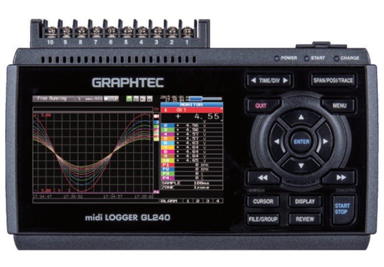
Graphtec GL240 10
- Wireless LAN capability | remote monitoring & datalogging
- Flexible input system for wide array of applications
- Ability to access additional (GL100) sensors & adapters
- Extended memory capacity using SD memory card
- Max sampling interval up to 10ms
Channels 4.3" Color Display Data Logger
Graphtec GL240 is a third-generation data logger product with exceptional price/performance. It’s a 10 analog channel device augmented by four discrete inputs and outputs. Its discrete inputs can be configured as a group to be either logic inputs or pulse inputs. When configured for pulse, each of the four channels can be configured to measure frequency or to count. The four discrete outputs are alarms that can be triggered by a variety of easily-defined analog and pulse/discrete input channel conditions. The 10 GL240 analog input channels may each be configured to measure a direct connected voltage in the range of 20 mV to 100 V full scale across 12 ranges, or for a direct-connected thermocouple of any type to measure temperature. Each of the GL240’s analog input channels is electrically isolated from other channels and from power ground allowing off-ground measurements using shunts, as well as powered or grounded thermocouples.
The most powerful GL240 feature is its triggering flexibility. Data recording can be independently started or stopped as a function of analog and pulse/discrete signal level (single or windowed), alarm, date and time, and day-of-the-week. Triggers can also be configured to operate only once, or to automatically repeat. The ability to of the GL240 to adapt to virtually any desired trigger condition allows the instrument to operate unattended for long periods of time with complete autonomy.
The GL240 operates either connected to a PC or entirely stand-alone. Connection to a PC may be over a standard USB or optional wireless connection. Either connection approach may take advantage of supplied PC-side software to configure, acquire, display, and record digitized information for storage directly to the PC’s HDD. Acquired data may be retrieved for review and analysis after recording, including the ability to export to Microsoft Excel. Using the GL240’s wireless option enables the instrument’s networking features, allowing it to be remotely configured and managed using the standard Web browser of any computer or smart phone. Automatic backup of data acquired to a user-accessible SD memory card is also supported via its FTP facility.
Finally, the measurement reach of a wireless-enabled GL240 is further extended by use of the GL100 accessory. The GL100 wirelessly enables measurements of temperature/humidity, acceleration, CO2, illuminance, ac current, and more. Communicate with up to (1) GL100 unit with B-568 Wifi module
Manufacturer Specs
|
Specifications |
|
|||
|
Number of analog input channels |
10 channels |
|
||
|
External input/ |
Input *2 |
Trigger or Sampling (1 channel), Logic/Pulse (4 channels) |
|
|
|
Output *3 |
Alarm (4 channels) |
|
||
|
Sampling interval |
10 ms to 1 hour (10ms to 50ms: voltage only) *4, External signal |
|
||
|
Time scale of waveform display |
1sec. to 24 hour /division |
|
||
|
Trigger, |
Trigger action |
Start or stop capturing data by the trigger |
|
|
|
Repeat action |
Off, On (auto rearmed) |
|
||
|
Trigger source |
Start: Off, Measured signal, Alarm, External, Clock, Week or Time |
|||
|
|
||||
|
Condition Setting |
Combination: OR or AND |
|
||
|
|
||||
|
|
||||
|
|
||||
|
Alarm output |
Outputs a signal when alarm condition occurs in the input signal *5 |
|
||
|
Pulse input |
Rotation count |
Counts the number of pulses per sampling interval and converts to rpm |
|
|
|
|
||||
|
|
||||
|
Accumulating |
Accumulates the number of pulses from the start of measurement |
|
||
|
|
||||
|
Instant count |
Counts the number of pulses per sampling interval |
|
||
|
|
||||
|
Calculation |
Between channels |
Addition, Subtraction, Multiplication, and Division for analog input |
|
|
|
Statistical |
Select two calculations from Average, Peak, Maximum, Minimum, RMS |
|
||
|
Search function |
Search for analog signal levels, values of logic or pulse or alarm point |
|
||
|
|
||||
|
Interface to PC |
USB (Hi-speed), WLAN (using B-568 option) |
|
||
|
Storage |
Media |
4 GB Internal Memory |
|
|
|
Saved contents |
Captured data, Setting conditions, Screen copy |
|
||
|
Capturing mode |
Mode: Normal, Ring, Relay |
|
||
|
|
||||
|
|
||||
|
Replay Data |
Replays captured data that was saved in the GL240 (in BGD or CSV format) |
|
||
|
Scaling (Engineering unit) function |
Measured value can be converted to the specified engineering unit |
|
||
|
|
||||
|
|
||||
|
|
||||
|
Action during data capture |
• Displaying parst data (using dual display mode (Current + Past data)) |
|
||
|
|
||||
|
|
||||
|
Display |
Size |
4.3-inch TFT color LCD (WQVGA: 480 x 272 dots) |
|
|
|
Language |
English, French, German, Chinese, Korean, Russian, Spanish, Japanese |
|
||
|
Information *8 |
Waveform in Y-T with digital values, Waveform only, Digital value, Digital values |
|
||
|
|
||||
|
Operating environment |
0 to 45 ºC, 5 to 85 % RH (non condensed) |
|
||
|
|
||||
|
Power source |
AC adapter |
100 to 240 V AC, 50/60 Hz (1 pc of adapter is attached as standard accessory) |
|
|
|
DC power |
8.5 to 24 V DC (DC drive cable (option B-514) is required) |
|
||
|
Battery pack |
Mountable battery pack (battery pack (option B-517): 7.2V DC, 2900mAh) |
|
||
|
Power consumption *9 |
Max. 36 VA |
|
||
|
External dimensions (W x D x H) |
Approx.188 x 117 x 42 mm (Excluding projections) |
|
||
|
Weight *10 |
500 g |
|
||
*1
Input/Output cable for GL (option B-513) is required to connect the signal.
*2
Input signal;
- Voltage range: Up to 24V (common ground)
- Signal type: Voltage, Open collector, Contact (relay)
- Threshold: Approx. + 2.5 V (Hysteresis: Approx. 0.5V (2.5V to 3V))
*3
Output signal: Open collector (pull-up to 5V by 10kΩ resistor)
- Voltage: Max. 30V
- Current: Max. 0.5A
- Collector dissipation: Max. 0.2W
*4
Minimum interval varies by number of channels used.
*5
Output port can be specified in each input channel.
*7
Size of the capture data will be limited to 1/3 of available memory.
*8
Display mode is switched every time the dedicated key is pressed. In magnified digital value mode, the displayed channel number can be specified. In the waveform display mode, the changing of the time scale will be effective from the point of the next displayed data.
*9
Rating under maximum power consumption using the AC adapter, with LCD display on, and battery pack being
charged.
*10
Excludes AC adapter and battery pack.
|
Software specifications for PC |
|
|||
|
Model name |
GL100_240_840-APS |
|
||
|
Supported OS |
Windows 8.1, 8, 7, Vista (32/64-bit edition) |
|
||
|
Supported device |
GL840 (USB, Ethernet, WLAN), GL240 (USB, WLAN), GL100 (USB, WLAN) |
|
||
|
Functions |
Control the GL series, Real-time data capture, Replay data, and Data format conversion |
|
||
|
Supported units & channels |
Up to 1000 channels total, Up to 4 groups (number of units is limited by model) |
|
||
|
Settings control |
Input condition, Captuering condition, Trigger/Alarm condition, Report, etc. |
|
||
|
Capturing data |
Saved to PC |
Saves captured data in real time (in GBD binary or CSV format) |
|
|
|
Saved to GL unit |
Saves to the SD memory card (in GBD binary or CSV format) |
|
||
|
Displayed information |
Y-T waveform, Digital values, Report, X-Y graph (specified period of data, data reply only), |
|||
|
|
||||
|
File operation |
Converting data format to CSV from GBD binary, merge multiple data files |
|
||
|
|
||||
|
Warning function |
Send e-mail to the specified address when the alarms occur |
|
||
|
Statistical calculation |
Maximum, Minimum, and Avarage during data capturing |
|
||
|
Report function |
Creates the daily or monthly report automatically |
|
||
|
Software specifications for Smart device |
|
|
Model name |
GL-Connect |
|
Supported OS |
Android 4.1 to 4.4, iOS 7/8 |
|
Supported device |
GL840 (WLAN), GL240 (WLAN), GL100 (WLAN) |
|
Functions |
Control the GL series, Display measured data in waveform or digital value |
|
Supported units |
Up to 10 units |
|
Settings control |
Start/Stop, Sampling interval |
|
Capturing data |
Saves captured data in the GL main body (data cannot be saved in the smart device) |
|
Displayed information |
Data captured in real time by digital value, Replay the data stored in the GL body by the waveform |
|
Wireless LAN unit (option) specifications |
|
||
|
Model number |
B-568 |
|
|
|
Supported GL series |
GL840, GL240 |
|
|
|
Communication method |
Wireless communication (using radio waves in the 2.4GHz band) |
|
|
|
Supported WLAN system |
IEEE802.11b/g/n |
||
|
|
|||
|
|
|||
|
|
|||
|
|
|||
|
Installed location |
Attached to the SD CARD slot number 2 on the GL840/GL240 |
|
|
|
|
|||
|
|
|||
|
Function |
Access Point mode: Communicate with the GL100-WL as a remote sensor |
|
|
|
|
|||
|
|
|||
|
|
|||
|
Connected number of GL100-WL |
GL840: Up to 5 units of the GL100-WL |
|
|
|
|
|||
|
GL240 Analog input specifications |
|
|||||
|
Input method |
All channels isolated balanced input *11, Scans channels for sampling |
|
||||
|
Type of input terminal |
Screw terminal (M3 screw) |
|
||||
|
Measurement |
Voltage |
20, 50, 100, 200, 500 mV, 1, 2, 5, 10, 20, 50, 100 V, and 1-5V F.S. (Full Scale) |
|
|||
|
Thermocouple |
Type: K, J, E, T, R, S, B, N, and W (WRe5-26) |
|
||||
|
Humidity |
0 to 100 % RH - using the humidity sensor (option B-530) |
|
||||
|
Filter |
Off, 2, 5, 10, 20, 40 (moving average in selected number) |
|
||||
|
Measurement |
Voltage |
± 0.1% of F.S. (Full Scale) |
|
|||
|
Temperature |
Type |
Measurement range |
Measurement accuracy |
|||
|
|
||||||
|
R |
0 ≤ TS ≤ 100 ºC |
± 5.2 ºC |
|
|||
|
100 < TS ≤ 300 ºC |
± 3.0 ºC |
|
||||
|
300 < TS ≤ 1600 ºC |
± (0.05% of rdg. + 2.0 ºC) |
|
||||
|
S |
0 ≤ TS ≤ 100 ºC |
± 5.2 ºC |
|
|||
|
100 < TS ≤ 300 ºC |
± 3.0 ºC |
|
||||
|
300 < TS ≤ 1760 ºC |
± (0.05% of rdg. + 2.0 ºC) |
|
||||
|
B |
400 ≤ TS ≤ 600 ºC |
± 3.5 ºC |
|
|||
|
600 < TS ≤ 1820 ºC |
± (0.05% of rdg. + 2.0 ºC) |
|
||||
|
K |
-200 ≤ TS ≤ -100 ºC |
± (0.05% of rdg. + 2.0 ºC) |
|
|||
|
-100 < TS ≤ 1370 ºC |
± (0.05% of rdg. + 1.0 ºC) |
|
||||
|
E |
-200 ≤ TS ≤ -100 ºC |
± (0.05% of rdg. + 2.0 ºC) |
|
|||
|
-100 < TS ≤ 800 ºC |
± (0.05% of rdg. + 1.0 ºC) |
|
||||
|
T |
-200 ≤ TS ≤ -100 ºC |
± (0.1% of rdg. + 1.5 ºC) |
|
|||
|
-100 < TS ≤ 400 ºC |
± (0.1% of rdg. + 0.5 ºC) |
|
||||
|
J |
-200 ≤ TS ≤ -100 ºC |
± 2.7 ºC |
|
|||
|
-100 < TS ≤ 100 ºC |
± 1.7 ºC |
|
||||
|
100 < TS ≤ 1100 ºC |
± (0.05% of rdg. + 1.0 ºC) |
|
||||
|
N |
-200 ≤ TS < 0 ºC |
± (0.1% of rdg. + 2.0 ºC) |
|
|||
|
0 ≤ TS ≤ 1300 ºC |
± (0.1% of rdg. + 1.0 ºC) |
|
||||
|
W |
0 ≤ TS ≤ 2000 ºC |
± (0.1% of rdg. + 1.5 ºC) |
|
|||
|
R.J.C. |
± 0.5 ºC |
|
||||
|
A/D converter |
Sigma-Delta type, 16 bits (effective resolution: 1/40000 of the measuring full range) |
|
||||
|
Maximum |
Between |
20 mV to 1 V range: 60 Vp-p, |
|
|||
|
|
||||||
|
Channels ((-) / (-)) |
60 Vp-p |
|
||||
|
Channel / GND |
60 Vp-p |
|
||||
|
Max. voltage |
Between channels |
350 Vp-p (1 minute) |
|
|||
|
Channel / GND |
350 Vp-p (1 minute) |
|
||||
*11
The terminal "b" for using the RTD is connected each other across all channels.
*12
Subject to the following conditions:
- Room temperature is 23 oC ± 5 oC.
- When 30 minutes or more have elapsed after power was turned on.
- Filter is set to 10.
- Sampling rate is set to 1 sec, using 10-channel.
- GND terminal is connected to ground.
*13
Wire size of thermocouple used is 0.32mm diameter in the T type and 0.65mm diameter in other types.
|
B-569 Optional Battery Information |
|
|
Item |
Description |
|
Capacity |
7.2V / 2900mAh |
|
Battery type |
Lithium secondary battery |
|
Running time |
When using the LCD display: approx. 6 hours |
|
Charging method |
Mount in the main unit |
|
Time required to charging |
approx. 4.5 hours |
|
Switch over in the event of a power failure |
Because the battery is used together with the AC adapter, the power supply will be switched automatically to the battery in the event of a power failure. |
|
Operation environment |
Running on battery: 0 to 40°C |
|
Other functions |
*When the battery is running low, file is closed automatically |
Tech Specs
|
Dataloggers / Data Acquisition/Data Recorders Template |
|
|
Type (Recorders) |
DAQ System, Data Logger, Videographic |
|
Style (Recorders) |
Behind Panel / DIN Rail Mount, Bench / Portable, PC Based |
|
# Channels Base Unit (Recorders) |
10 EA |
|
Display (Recorders) |
Built-in, Included w/ Base Unit |
|
# Logic / Digital Channels |
4 channels |
|
Sampling Interval (Controllers/Recorders) |
10 ms |
|
Sampling Frequency (Recorders) |
100 S/s (0.0001 MS/S) |
|
Input Types (Controllers/Recorders) |
Current / 4-20 mA, Digital / Logic / On-Off, Frequency / Pulse, T/C - RTD, Voltage |
|
Output Types (Controllers/Recorders) |
Relay |
|
Bits |
16 |
|
Power Source |
AC Line, Battery, DC Line |
|
Screen Size |
4.3 IN |
|
Special Functions (Recorders) |
External Trigger, Flow / Speed Totalization, Logic / Ladder / Math, PC Software Available, Software / Visible Alarms |
|
Data storage |
Yes |
|
Isolated Inputs (Recorders) |
Yes |
|
Accuracy |
Voltage: ±0.1% of Full Scale |